Running their stepper with the provided driver is a simple task.

Here is a picture of the OSEPP driver:
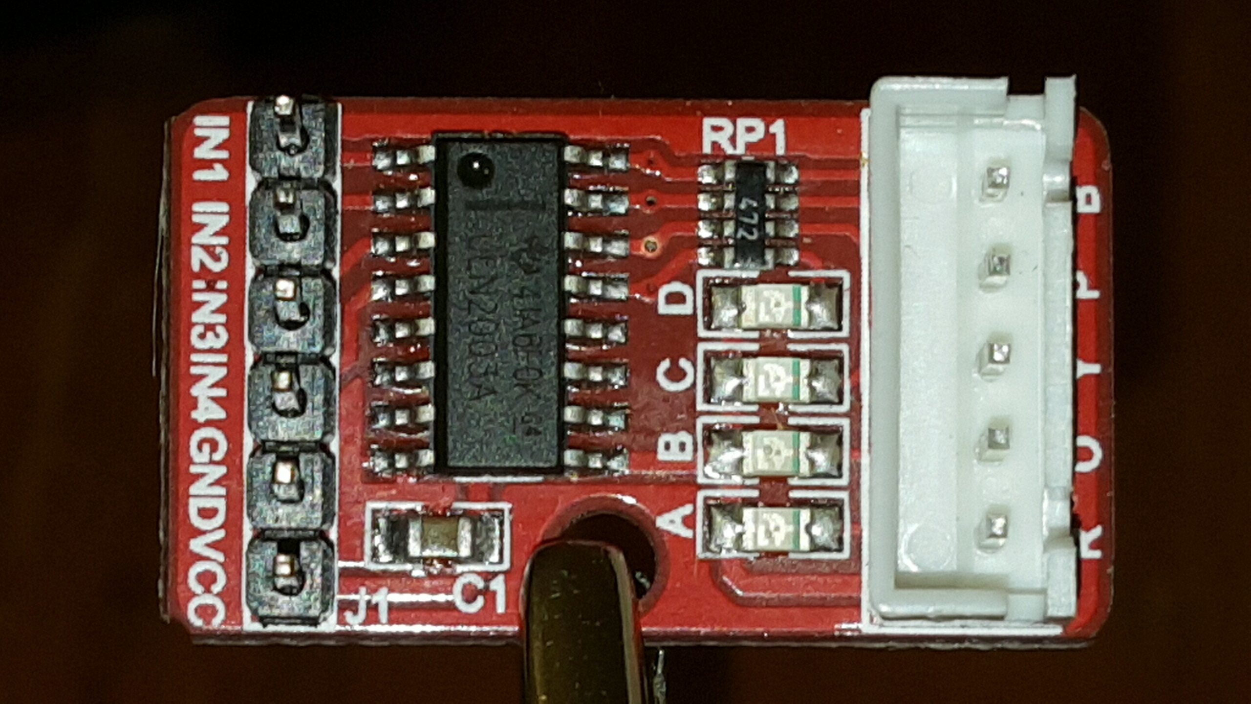
The large IC in the driver is a ULN2003A Darlington Transistor Array. In addition to that, there is a set of LEDs which show which of the signals is active. I'm not sure what the component labelled RP1 is, though I assume a bank of resistors for the LEDs.
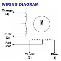
Now the motor itself is a unipolar stepper motor which means that there are two coils, each with a common center tap. The two common center tap wires are tied together, which means that there are 5 wires for this motor. The red lead is the common center tap which should be attached to VCC. The pink and orange leads are the wires for one of the coils and the yellow and blue leads are for the other coil.
A very good description about how this motor works and how to drive it using a ULN2003A transistor array comes from Bret Stateham and is available on YouTube at https://www.youtube.com/watch?v=B86nqDRskVU.
For the video above, I used a simple Adrunio Sketch that used the
Stepper class to run the motor. Here is my own slightly modified version of the original sketch
#include <stepper.h>

int stepIN1Pin = 8;
int stepIN2Pin = 9;
int stepIN3Pin = 10;
int stepIN4Pin = 11;

int stepsPerRevolution = 2048;

Stepper myStepper(stepsPerRevolution,
                  stepIN1Pin, stepIN3Pin,
                  stepIN2Pin, stepIN4Pin);

void setup()
{
    // set the RPM
    myStepper.setSpeed(12);
}

void loop()
{
    // step one revolution in one direction
    myStepper.step(stepsPerRevolution);
    // wait a second
    delay(100);

    // step one revolution in the other direction
    myStepper.step(-stepsPerRevolution);
    // wait a second
    delay(100);
}
This seems to work well enough to just turn the motor forwards and backwards, but can I actually use this to do something useful?
Here's something interesting about the numbering of the output pins. The globals
stepIN1Pin, etc. define pin 1-4 as being on GPIO outputs 8-11. However when passing the GPIO pin assignments to the constructor of Stepper, the assignments are:Stepper myStepper(stepsPerRevolution,
stepIN1Pin,
stepIN3Pin,
stepIN2Pin,
stepIN4Pin)
Note how the ordering is different. Tracing the wires, I find that the blue lead from the motor is assigned to GPIO 8, the orange to GPIO pin 9, the yellow to GPIO pin 10, and the orange to GPIO 11.
I hooked my scope up to the circuit to see how the Stepper class drives the output signals.

You can see the operation of the full stepping in this image. Each coil is high for 2 cycles, followed by 2 low cycles. The period of a full iteration through the stepping progression is 8.2ms, so each cycle here is around 2.05ms, which is about as fast as this motor can drive.
No comments:
Post a Comment