I've recently been going through a tutorial series on programming for the AVR in assembly language. I found this tutorial on Instructables, and have found it really fascinating.
The Arduino IDE certainly makes programming the Arduino easy, but I really enjoy the nuts and bolts of it all. I suppose that is why I like to play with electronics and computers in the first place. So I've never really been one who enjoys black boxes, but rather, I always like to crack open the box and understand what makes it tick.
Also, I've been using a breadboard-based microcontroller lately, rather than hooking up a circuit to a pre-fab Arduino board. There are instructions for how to create a breadboard arduino on the arduino.cc site at https://www.arduino.cc/en/Main/Standalone.
The latest gadget I built was an electronic dice roller, based on the 4th tutorial in the series. The microcontroller is attached to two banks of LEDs in the shape of a pair of dice. The anode of each dot in one die is wired to a pin on the ATmega328 and also to the anode of the corresponding dot on the other die. So the LEDs of the middle dots of both dice are wired together and then wired to the microcontroller with a single wire. The cathodes of all of the LEDs on one die are also tied together, and then wired back to a single pin on the MCU through a 330 Ohm resistor. The cathodes of each die are tied to a different pin. By alternating which pin is active, the program can alternate which die is lit. When die 1 is lit, it activates the appropriate dots for that die. When die 2 is lit, it activates a different set of dots. As it does this fast enough, the eye does not notice and thus 14 LEDs are controlled by 9 pins.
If you're interested in seeing it in action, I've included a video.
As an aside from doing Arduino projects with robotics, I have been building some other random circuits and experimenting with different components. Today I built an Analog to Digital converter based on a design I found in some class materials from the University of Pennsylvania. Specifically, one of the lab assignments for their ESE206 class had the students build an Analog to Digital converter.
I'd previously worked with the analog input pins of the Arduino and know that they have a built-in 10-bit analog to digital converter, but I wanted to see if I could build this circuit from discrete components. I happened to have the LM339 Comparator that is at the heart of this circuit.
Now this is basically a 4-bit ADC, so clearly it isn't super useful for real signal sampling applications, but it does illustrate the basics of analog to digital conversion.
I have a nice 5V power supply that I use for most of my circuits but this circuit asked for a Vcc of +15V. At some point, I'd like to have a nice adjustable bench power supply with multiple outputs, but today I don't have that luxury. However, I was able to make this circuit work just fine using my simple 5V supply by replacing the 12kΩ resistor between the top comparator and the supply voltage with a 1kΩ resistor.
For the Vin I made a simple voltage divider circuit consisting of a 1kΩ resistor in series with a 10kΩ potentiometer.
Also, for fun I hooked it up to the output of the FG085 Function Generator from JYE Tech. With a sufficiently slow signal, we can watch the LEDS light up in order!
I also decided to try hooking the ADC up to my Rigol DS-1054Z Oscilloscope. With the LEDs as output indicators we can visualize waves up to about 5Hz. That is, we can see how the low bit turns on before the higher bits. After that it just looks like rapidly flashing LEDs, and after about 30Hz, they basically appear to be on all the time. I generated a 100kHz sine wave with my function generator and looked at 3 of the 4 output bits on the scope.
At this speed one can readily see the rise and fall time of the ADC converter. This is especially noticable in the following close up:
After some thought, I see that calling this circuit a 4-bit ADC is not quite correct. Once would expect a 4-bit ADC capable of sampling the input and producing an output signal with 24 different possible values. My circuit can only produce 5 possible output values 0 LEDs on up to 4 LEDs on, so this is really not even a 3-bit ADC.
Also, using the cursor feature on the scope, I can see the input levels needed to drive each of the output signals high:
After the disappointment of trying to use the 28BYJ-48 as a drive motor for my robot, I purchased some DC Gearbox motors from Pololu to use as drive motors. These motors are a bit pricey at $36.95 each, but they are powerful, and have built-in encoders for monitoring the rotation.
I built a test circuit using a L293D H-Bridge integrated circuit. My initial circuit was quite simple. The L293D has 2 independent H-Bridges which can control 2 motors. Each motor has 2 inputs which are signals from the controller. In my case, the controller was an Arduino using PWM (pulse width modulation) outputs. The chip then has 2 outputs which can drive the motor using a high voltage, high current source, VS, which can be up to 36V according to the data sheet.
Previously, I explored running a stepper motor using
the Arduino Uno, an OSEPP stepper motor driver and the Stepper
class provided as part of the Arduino class library. Any interesting robotics
project will likely involve reading multiple sensors, and also controlling
multiple motors, so it is important that the microcontroller be able to
multi-task and not be tied up performing any single operation. Unfortunately, I
have found that the library Stepper class, while quite useful and instructive,
does tend to monopolize the microcontroller CPU.
Consider the following function which is at the heart of the stepper control
process:
void Stepper::step(int steps_to_move)
{
  int steps_left = abs(steps_to_move);  // how many steps to take

  // determine direction based on whether steps_to_mode is + or -:
  if (steps_to_move > 0) {this->direction = 1;}
  if (steps_to_move < 0) {this->direction = 0;}

  // decrement the number of steps, moving one step each time:
  while(steps_left > 0) {
    // move only if the appropriate delay has passed:
    if (millis() - this->last_step_time >= this->step_delay) {
      // get the timeStamp of when you stepped:
      this->last_step_time = millis();
      // increment or decrement the step number,
      // depending on direction:
      if (this->direction == 1) {
        this->step_number++;
        if (this->step_number == this->number_of_steps) {
          this->step_number = 0;
        }
      } else {
        if (this->step_number == 0) {
          this->step_number = this->number_of_steps;
        }
        this->step_number--;
      }
      // decrement the steps left:
      steps_left--;
      // step the motor to step number 0, 1, 2, or 3:
      stepMotor(this->step_number % 4);
    }
  }
}
The above code is from
arduino-1.6.4/libraries/Stepper/src/Stepper.cpp which is published
under the GNU LGPL
Notice how lines 10-12 essentially create a busy-loop, which does not return
from the function until the desired number of steps have been reached. This is
fine if your microcontroller only needs to concern itself with running the
stepper motor (interrupts not withstanding). But overall, I'd prefer to have
something more asynchronous, which is able to respond to and process other
stimulus while still being able to handle the switching needed to drive the
stepper motor(s).
A dual motor driver program
I decided to explore what would be involved in running two steppers at once
from the same microcontroller. Clearly, the code will need to be more
asynchronous and not busy-loop in order to operate more than one drive motor.
Instead of having a function which polls the clock in a loop to see when to
adjust the output levels, I want to have a Motor class which keeps
the state of the motor and a class method that is called periodically
(frequently, on a timer) and checks the clock to see if enough time has elapsed
since the last time the motor was stepped. If it is time to update the voltage
levels on the pins, it will perform the step operation, otherwise the call is
a no-op
The heart of the Motor class I have written is shown below:
void Motor::tick() {
    unsigned long now = micros();

    if (now - lastStepTime > cycleDuration) {
        doStep();
        lastStepTime = now;
    }
}
The setup() function becomes:
Motor *m1 = NULL, *m2 = NULL;

void setup() {
    m1 = new Motor(4, 6, 5, 7);
    m1->setCycleDuration(2300);
    m2 = new Motor(8, 10, 9, 11);
    m2->setCycleDuration(4600);
}
The 4 parameters to the Motor constructor are the numbers of the 4 GPIO
pins that are connected to the motor, and the cycleDuration is the number
of microseconds which must elapse between steps. In this case, the code is creating
two Motor objects, one of which is attached to pins 4-7 and the other of which is
attached to pins 8-11. The cycle duration on motor 1 is set to be 2300us, and the second
motor is set to have a time of 4600us between steps, so motor 1 will rotate twice as
fast as motor 2.
The complete code for this project is on GitHub at
TwoMotorControl.cpp.
The GitHub project for this code also contains a Makefile which allows me to build and upload
the code to my Arduino Uno outside of the Arduino IDE.
Building the Circuit
I wired up a circuit using the following parts:
Arduino Uno compatible board
2 28BYJ-48 Stepper Motors
ULN2803a Darlington Transistor array IC which allows the signals from the microcontroller to switch the coils in the motors
9V battery to provide power to the motors
LM7805 voltage regulator to provide 5V Vcc to the motors.
In a previous post I discussed
using a Darlington transistor array to drive a single 28BYJ-48 Motor.
The wiring of the project is shown in the two following Fritzing diagrams
Apologies if the wiring is confusing, this was my first time producing a circuit diagram with Fritzing!
The video below shows the two motors being driven at different rates of speed using a single controller.
The end goal of this project of course is to build an autonomous robot, so I attached the motors to a frame that my son and I built from
the parts of a couple of Erector sets. The images below show some details regarding the construction of the robot base. One of the more interesting
features of this robot is the rotating third wheel.
The good news is that the motors were able to turn the wheels at different speeds (when the wheels had no
resistance.) The unfortunate part of this experiment was that the 28BYJ-48 motors proved to be underpowered
to drive the robot base we had constructed. This inital robot design has 2 drive motors which are directly connected
to Erector wheels, and a third wheel in the front of the robot which is mounted on a swivel mechanism which should
allow the front wheel to rotate freely. As it became clear, even when the controller is driving the right wheel twice as
fast as the left wheel, the resistance from the front wheel and opposite wheel prevent the robot from making a left
turn as I had expected it would do given the distribution of force.
Well, I seem to have run into a dead end when it comes to driving a motor using the Arduino kit and drivers, but no fear... I
just got 2 very nice brushed DC motors from Pololu and plan to try driving the motors with that device next.
When doing software development for Arduino, there is no doubt that the Arduino IDE is a nice tool for getting up and running quickly. For people with less experience in software development, it might even be the best way to code for the Arduino. However, having done C/C++ development for 25 years, I find that I miss my preferred editor. I also am comfortable with Make, so I decided to see if I could create my own makefiles for building for Arduino.
I had previously found Other Projects for using Make to build for the Arduino. Unfortunately, I don't think this project is what I'm looking for. I'd really like a small (one-page) Makefile that I can wrap my head around. The Arduinio.mk in the sudar/Arduino-Makefile project is over 1,500 lines. I'm sure it is very full featured and robust, but not something that I want to start hacking on.
I took the sketch for my Stepper Motors sketch and built it clean using the Arduino IDE. Then looked at the build commands it ran, and created a Makefile to replicate its build process. I extracted some paths and some other things to variables which could be tweaked. The resulting Makefile is short and succinct (though at 75 lines still may be a bit more than what fits on a single page).
I began my exploration of stepper motors by building the circuit described in the OSEPP Learn Arduino Basics book. The Arduino Basics Starter Kit they sell comes with a 28BYJ-48 stepper motor, which is a nice little low-cost and basic stepper. It also comes with a small stepper motor driver board containing a ULN2003A Darlington Transistor array.
Running their stepper with the provided driver is a simple task.
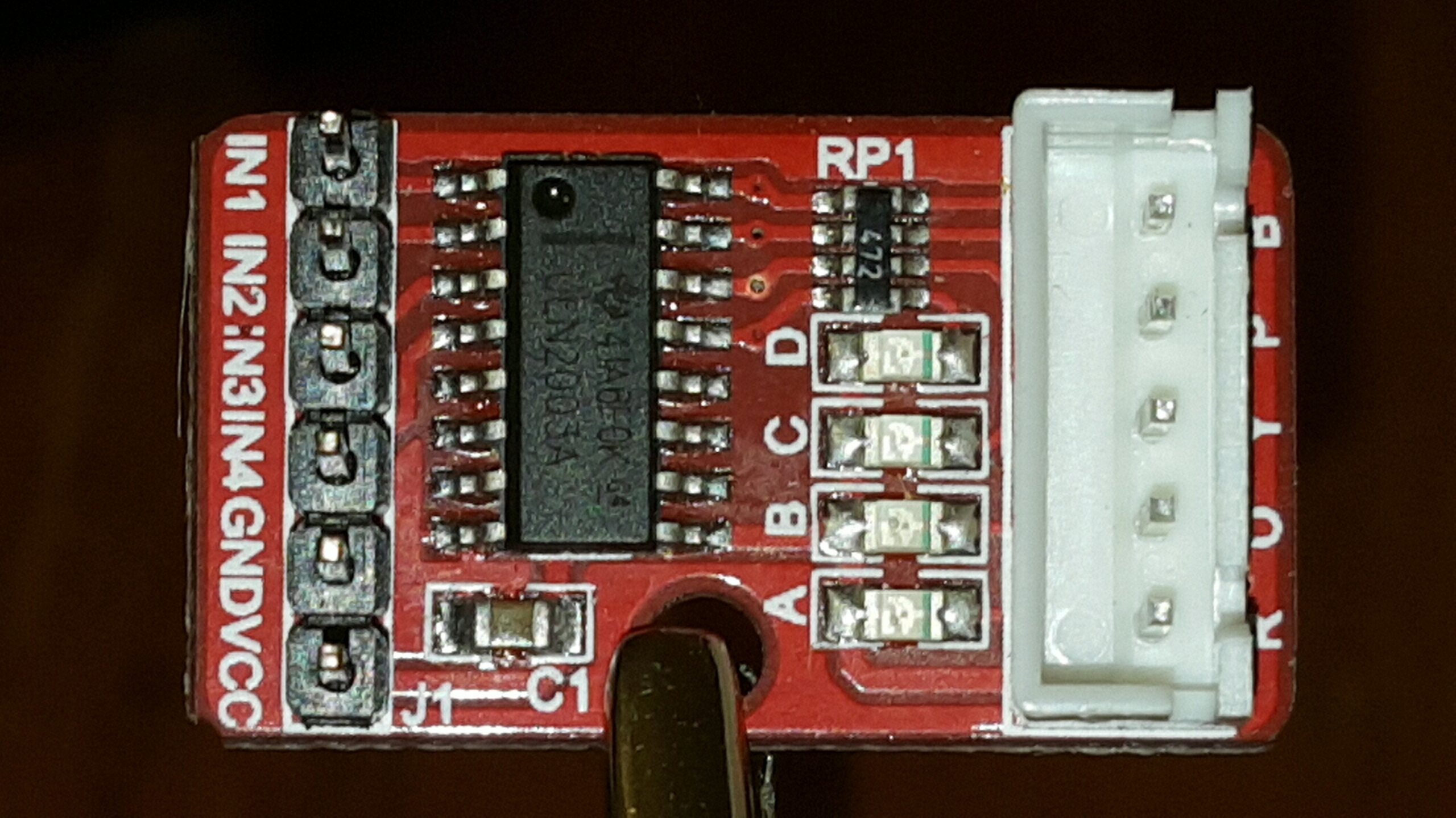
Here is a picture of the OSEPP driver:
The large IC in the driver is a ULN2003A Darlington Transistor Array. In addition to that, there is a set of LEDs which show which of the signals is active. I'm not sure what the component labelled RP1 is, though I assume a bank of resistors for the LEDs.
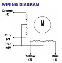
Now the motor itself is a unipolar stepper motor which means that there are two coils, each with a common center tap. The two common center tap wires are tied together, which means that there are 5 wires for this motor. The red lead is the common center tap which should be attached to VCC. The pink and orange leads are the wires for one of the coils and the yellow and blue leads are for the other coil.
A very good description about how this motor works and how to drive it using a ULN2003A transistor array comes from Bret Stateham and is available on YouTube at https://www.youtube.com/watch?v=B86nqDRskVU.
For the video above, I used a simple Adrunio Sketch that used the Stepper class to run the motor. Here is my own slightly modified version of the original sketch
#include <stepper.h>

int stepIN1Pin = 8;
int stepIN2Pin = 9;
int stepIN3Pin = 10;
int stepIN4Pin = 11;

int stepsPerRevolution = 2048;

Stepper myStepper(stepsPerRevolution,
                  stepIN1Pin, stepIN3Pin,
                  stepIN2Pin, stepIN4Pin);

void setup()
{
    // set the RPM
    myStepper.setSpeed(12);
}

void loop()
{
    // step one revolution in one direction
    myStepper.step(stepsPerRevolution);
    // wait a second
    delay(100);

    // step one revolution in the other direction
    myStepper.step(-stepsPerRevolution);
    // wait a second
    delay(100);
}
This seems to work well enough to just turn the motor forwards and backwards, but can I actually use this to do something useful?
Here's something interesting about the numbering of the output pins. The globals stepIN1Pin, etc. define pin 1-4 as being on GPIO outputs 8-11. However when passing the GPIO pin assignments to the constructor of Stepper, the assignments are:
Note how the ordering is different. Tracing the wires, I find that the blue lead from the motor is assigned to GPIO 8, the orange to GPIO pin 9, the yellow to GPIO pin 10, and the orange to GPIO 11.
I hooked my scope up to the circuit to see how the Stepper class drives the output signals.
You can see the operation of the full stepping in this image. Each coil is high for 2 cycles, followed by 2 low cycles. The period of a full iteration through the stepping progression is 8.2ms, so each cycle here is around 2.05ms, which is about as fast as this motor can drive.
The Adafruit lesson suggests a PN2222 transistor, but I used a 2N3904 transistor, which is also a NPN type transistor. My understanding is that the primary difference between them is the amount of current that they can handle, the PN2222 being able to support more current. The datasheet says that the 2N3904 has a maximum collector current (IC) of 200 mA, which should be sufficient to drive a small DC motor.
The diode is a very important part of the circuit and protects your Arduino from currents coming from the inductive load of the motor.
I used the code from the sketch on the Adafruit site. This reads a value from the serial input and uses that to set the level on a PWM (pulse width modulation) output pin. I'll talk more about PWM later.
It was interesting to see how different values were able to run the motor at different speeds. For fun, I hooked this circuit up to a Rigol DS1054Z Oscilloscope to see the signals at the PWM output and also across the motor itself.