Previously, I explored running a stepper motor using
the Arduino Uno, an OSEPP stepper motor driver and the Stepper
class provided as part of the Arduino class library. Any interesting robotics
project will likely involve reading multiple sensors, and also controlling
multiple motors, so it is important that the microcontroller be able to
multi-task and not be tied up performing any single operation. Unfortunately, I
have found that the library Stepper class, while quite useful and instructive,
does tend to monopolize the microcontroller CPU.
Consider the following function which is at the heart of the stepper control process:
void Stepper::step(int steps_to_move)
{
  int steps_left = abs(steps_to_move);  // how many steps to take

  // determine direction based on whether steps_to_mode is + or -:
  if (steps_to_move > 0) {this->direction = 1;}
  if (steps_to_move < 0) {this->direction = 0;}

  // decrement the number of steps, moving one step each time:
  while(steps_left > 0) {
    // move only if the appropriate delay has passed:
    if (millis() - this->last_step_time >= this->step_delay) {
      // get the timeStamp of when you stepped:
      this->last_step_time = millis();
      // increment or decrement the step number,
      // depending on direction:
      if (this->direction == 1) {
        this->step_number++;
        if (this->step_number == this->number_of_steps) {
          this->step_number = 0;
        }
      } else {
        if (this->step_number == 0) {
          this->step_number = this->number_of_steps;
        }
        this->step_number--;
      }
      // decrement the steps left:
      steps_left--;
      // step the motor to step number 0, 1, 2, or 3:
      stepMotor(this->step_number % 4);
    }
  }
}
The above code is from
arduino-1.6.4/libraries/Stepper/src/Stepper.cpp which is published
under the GNU LGPL
Notice how lines 10-12 essentially create a busy-loop, which does not return from the function until the desired number of steps have been reached. This is fine if your microcontroller only needs to concern itself with running the stepper motor (interrupts not withstanding). But overall, I'd prefer to have something more asynchronous, which is able to respond to and process other stimulus while still being able to handle the switching needed to drive the stepper motor(s).
A dual motor driver program
I decided to explore what would be involved in running two steppers at once from the same microcontroller. Clearly, the code will need to be more asynchronous and not busy-loop in order to operate more than one drive motor.
Instead of having a function which polls the clock in a loop to see when to
adjust the output levels, I want to have a Motor class which keeps
the state of the motor and a class method that is called periodically
(frequently, on a timer) and checks the clock to see if enough time has elapsed
since the last time the motor was stepped. If it is time to update the voltage
levels on the pins, it will perform the step operation, otherwise the call is
a no-op
The heart of the Motor class I have written is shown below:
void Motor::tick() {
    unsigned long now = micros();

    if (now - lastStepTime > cycleDuration) {
        doStep();
        lastStepTime = now;
    }
}
The setup() function becomes:
Motor *m1 = NULL, *m2 = NULL;

void setup() {
    m1 = new Motor(4, 6, 5, 7);
    m1->setCycleDuration(2300);
    m2 = new Motor(8, 10, 9, 11);
    m2->setCycleDuration(4600);
}
The 4 parameters to the Motor constructor are the numbers of the 4 GPIO
pins that are connected to the motor, and the cycleDuration is the number
of microseconds which must elapse between steps. In this case, the code is creating
two Motor objects, one of which is attached to pins 4-7 and the other of which is
attached to pins 8-11. The cycle duration on motor 1 is set to be 2300us, and the second
motor is set to have a time of 4600us between steps, so motor 1 will rotate twice as
fast as motor 2.
With this setup, the standard loop() function is:
void loop() {
    m1->tick();
    m2->tick();
    delayMicroseconds(10);
}
The complete code for this project is on GitHub at TwoMotorControl.cpp. The GitHub project for this code also contains a Makefile which allows me to build and upload the code to my Arduino Uno outside of the Arduino IDE.
Building the Circuit
I wired up a circuit using the following parts:
- Arduino Uno compatible board
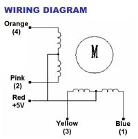
- 2 28BYJ-48 Stepper Motors
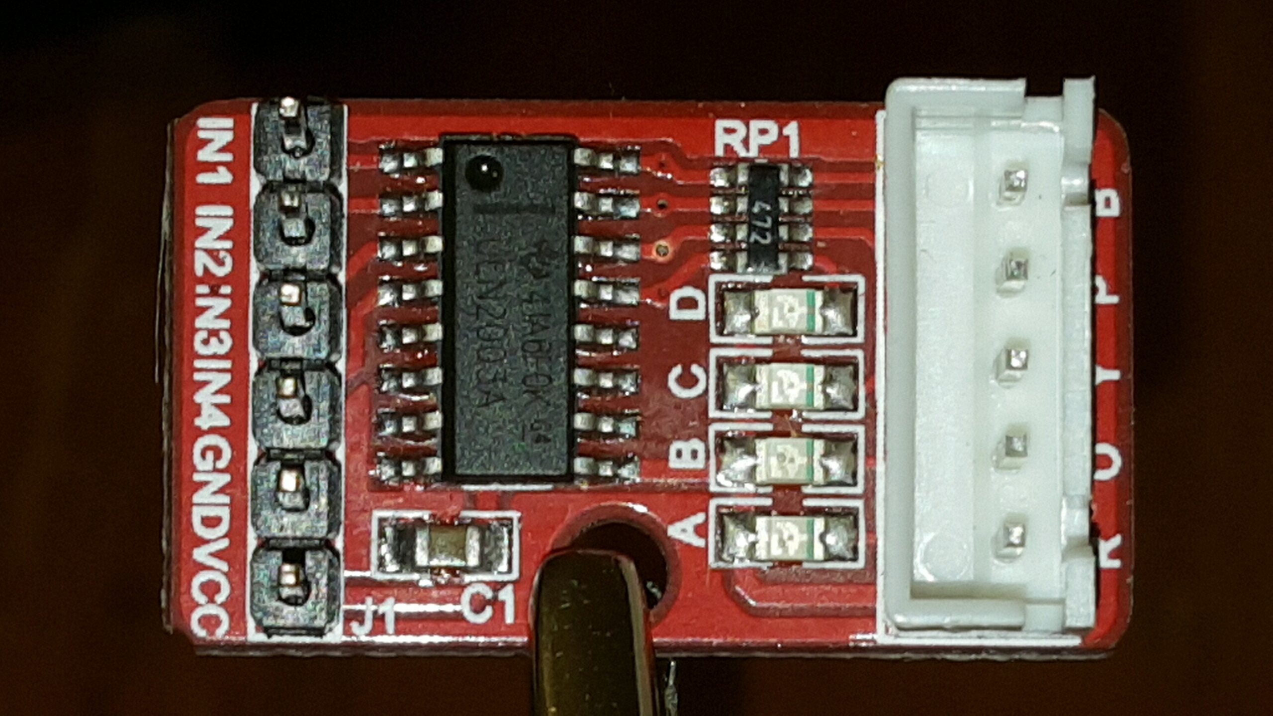
- ULN2803a Darlington Transistor array IC which allows the signals from the microcontroller to switch the coils in the motors
- 9V battery to provide power to the motors
- LM7805 voltage regulator to provide 5V Vcc to the motors.
In a previous post I discussed using a Darlington transistor array to drive a single 28BYJ-48 Motor.
The wiring of the project is shown in the two following Fritzing diagrams


Apologies if the wiring is confusing, this was my first time producing a circuit diagram with Fritzing!
The video below shows the two motors being driven at different rates of speed using a single controller.
The end goal of this project of course is to build an autonomous robot, so I attached the motors to a frame that my son and I built from the parts of a couple of Erector sets. The images below show some details regarding the construction of the robot base. One of the more interesting features of this robot is the rotating third wheel.


The good news is that the motors were able to turn the wheels at different speeds (when the wheels had no resistance.) The unfortunate part of this experiment was that the 28BYJ-48 motors proved to be underpowered to drive the robot base we had constructed. This inital robot design has 2 drive motors which are directly connected to Erector wheels, and a third wheel in the front of the robot which is mounted on a swivel mechanism which should allow the front wheel to rotate freely. As it became clear, even when the controller is driving the right wheel twice as fast as the left wheel, the resistance from the front wheel and opposite wheel prevent the robot from making a left turn as I had expected it would do given the distribution of force.
Well, I seem to have run into a dead end when it comes to driving a motor using the Arduino kit and drivers, but no fear... I just got 2 very nice brushed DC motors from Pololu and plan to try driving the motors with that device next.